
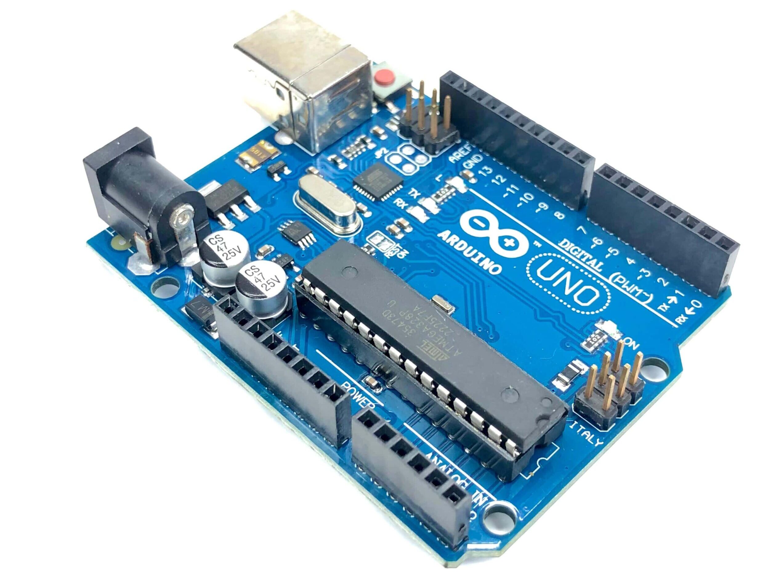
Arduino UNO is a microcontroller board based on the ATmega328P. It has 14 digital input/output pins (of which 6 can be used as PWM outputs), 6 analog inputs, a 16 MHz ceramic resonator, a USB connection, a power jack, an ICSP header and a reset button. It contains everything needed to support the microcontroller; simply connect it to a computer with a USB cable or power it with a AC-to-DC adapter or battery to get started. You can tinker with your UNO without worrying too much about doing something wrong, worst case scenario you can replace the chip for a few dollars and start over again.

The UNO board is the flagship product of Arduino. Regardless if you are new to the world of electronics or will use
the UNO as a tool for education purposes or industry-related tasks, the UNO is likely to meet your needs.
First entry to electronics: If this is your first project within coding and electronics, get started with our most used
and documented board; Arduino UNO. It is equipped with the well-known ATmega328P processor, 14 digital
input/output pins, 6 analog inputs, USB connections, ICSP header and reset button. This board includes everything
you will need for a great first experience with Arduino.
Industry-standard development board: Using the Arduino UNO R3 board in industries, there are a range of
companies using the UNO board as the brain for their PLC’s.
Education purposes: Although the UNO R3 board has been with us for about ten years, it is still widely used for
various education purposes and scientific projects. The board’s high standard and top quality performance makes it
a great resource to capture real time from sensors and to trigger complex laboratory equipment to mention a few
examples.

Features
ATMega328P Processor
Memory
AVR CPU at up to 16 MHz
32KB Flash
2KB SRAM
1KB EEPROM
Security
Power On Reset (POR)
Brown Out Detection (BOD)
Peripherals
2x 8-bit Timer/Counter with a dedicated period register and compare channels
1x 16-bit Timer/Counter with a dedicated period register, input capture and compare channels
1x USART with fractional baud rate generator and start-of-frame detection
1x controller/peripheral Serial Peripheral Interface (SPI)
1x Dual mode controller/peripheral I2C
1x Analog Comparator (AC) with a scalable reference input
Watchdog Timer with separate on-chip oscillator
Six PWM channels
Interrupt and wake-up on pin change
ATMega16U2 Processor
8-bit AVR® RISC-based microcontroller
Memory
16 KB ISP Flash
512B EEPROM
512B SRAM
debug WIRE interface for on-chip debugging and programming
Power : 2.7-5.5 volts
2 Ratings
2.1 Recommended Operating Conditions
Symbol Description Min Max
Conservative thermal limits for the whole board: -40 °C (-40°F) 85 °C ( 185°F)
NOTE: In extreme temperatures, EEPROM, voltage regulator, and the crystal oscillator, might not
work as expected.
2.2 Power Consumption
Symbol Description Min Typ Max Unit
VINMax Maximum input voltage from VIN pad 6 – 20 V
VUSBMax Maximum input voltage from USB connector – 5.5 V
PMax Maximum Power Consumption – – xx mA
